Saturday, December 22, 2012

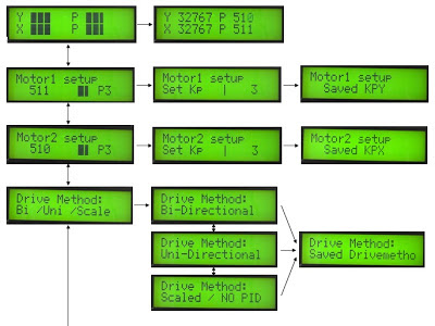
AMC644USB 6DOF firmware menu system features

Hi,

I just finished the coding for the user menu of the 6DOF addon and I made a short (?) video explaining its operation:

Or here stabilized version: http://www.youtube.com/watch?v=Z47_-_X7YBE

Available options on the menu system are:
1. How many DOF (degrees of freedom), 2DOF - 6DOF.
2. Resolution of data format from PC, 16-bit (65535 positions) or 8-bit (256 positions).
3. PID settings for all terms, P, I and D.
4. Max speed of the motors.
5. Min speed of the motors.
6. Limits of the feedback devices (potentiometers or hall effect)

Among others, depending on the DOF (number of motors) that are used and the resolution, it runs the position control algorithms from 1000 to 3600 times per second. I had to sacrifice some speed over safety and accuracy. But the fact that the speed is adjustable by how many motors are being used is more than great!


Sunday, December 16, 2012

A test of the 6DOF hardware with Ian's 6DOF BFF software

Hi,

Today I performed some tests of the 6DOF hardware on Ian's 6DOF BFF motion software successfully. He added just yesterday a new 16-bit data format just for my 6DOF hardware (BIN2TH).

I run the tests with 230Kbps serial speed.

Flight tests on FSX using 6DOF BFF


Ground effects test using 6DOF BFF

This is a great software. After you set correctly all the dimensions of the actuators and the platform it works pretty much out of the box.

Thanks Ian!!


Friday, December 14, 2012

6DOF extension board visual demonstration

On waiting for the 6DOF extension boards to arrive, I did some more testing on the 6DOF code and took the opportunity to make a little video:


The six axis where connected to x-sim receiving 16-bit positioning values on 230Kbps. I set the sliders to move automatically. I hooked up only three potentiometers, that's why the last three axis feedback show full value. For the analog and digital outputs I used some led strips.


Thanos

Saturday, December 8, 2012

New speed tests with 6DOF code

Hi,

Today I made new tests with the 6DOF code to see the response while having to receive data for 6 motors. I did tests with 8-bit data (256) and 16-bit data (65535).

I got similar response timing with my old code that was only for 2DOF. And there is almost no difference having to deal with 8-bit and 16-bit format data for each axis. The program loop speed now is 4Khz (or 4000 times per second).

New LCD layout to display all 6 axis (6DOF) 

6DOF 8-bit data (256) timing using 115kbps serial speed


6DOF 8-bit data (256) timing using 230kbps serial speed


6DOF 16-bit (65535) timing using 230kbps serial speed

As you can see in the timing captures I fixed the introduced delay that existed until the whole data packet was received. So the loop cycle timing remains constant always.


Thanos

Monday, November 26, 2012

Something new is coming...

I got some extra outputs available... say 6 analog and 12 digital...

Anyone for a 6DOF extension?


Thanos

Tuesday, November 20, 2012

What's the purpose of AMC644USB?


Many misunderstand the purpose of the AMC644USB board and what exactly it does. 

First of all, the VFD inverters are just speed drivers for the AC motors meaning that they only set the speed and the direction of the motor. They are not intelligent in any way to be able to determine the position of the motor or place the motor to curtain position. Some inverters have feedback from the motor just to verify the correct speed. Even if you connected them to a computer through a RS485 interface the only thing you can do is to adjust their speed.

This is where AMC644USB comes into to fill in that missing link of motion control. The AMC644USB receives the motion data from the computer (positions) in high speeds of 1ms intervals, then creates the proper voltages and signals to set the correct speed and direction needed from the inverters and then reads the position of the motors using the potentiometers or any other encoders attached on the motors as feedback to precisely stop each motor to the desired position. These positioning calculations are performed 5000 times per second that gives fine positioning resolution and very fast reaction times.


Monday, November 19, 2012

Real Breakthrough In Speed (again)

Hi,

I was looking for a way to make ADC more immune to noise and during this search I managed to increase the speed of the ADC routine to a level that now takes only 26us to sample each ADC channel (before 192us was spend in ADC sampling for each channel). The noise is eliminated now so I had to run some speed tests again to see the overall improvement.

With this improvement now, the total program cycle delay is only 200us average. The firmware now runs 5000 times per second (average) which is 5Khz, while the first release of this firmware was limited only to 1000 times per second (1Khz).

Not to mention that the above readings are with the LCD user menu active, running in realtime along the rest of the code.


This is a capture with a logic analyzer of a serial packet (230kbps) along the program cycle speed.


Wider view of the capture above to get a good idea how fast is the cycle speed now.


So now using ADC as position input feedback for the motors, the total loop is as fast as with digital encoders.

Thanks for reading this,

Thanos

Wednesday, November 14, 2012

New speed measures on latest firmware 1.2e

Hi,

It was time to test new higher serial baud rate speeds today. I reached up to 230400bps with no problems. I used a logic analyzer to capture the serial input next to the loop cycle of the firmware.

I got a really good surprised by the results as with the constant improvements, I forgot to check how fast the main loop speed was going.

Just to say that now the refresh rate is 1666 times per second!!! So the main loop is running now in 1.666KHz !!

Also you may notice that since the serial input is not reside on the main loop but in an interrupt, the main loop is actually faster than the 1KHz update rate of the serial data.


Have a look on the capture screens for 115200bps and 230400bps speed.

 115kbps serial speed detail

  115kbps serial speed 


~


  230kbps serial speed detail

 230kbps serial speed


The above measurements are with ADC inputs as position input.

Now lets see what happens with digital encoder as position inputs:


The average loop cycle of the main program is around 5000 times per second now (5KHz). The variation is because of the extra delay introduced during receiving data packets.


Thanks for looking,
Thanos

Tuesday, October 23, 2012

Got Manual yet?

Hi,

After a lots of revisions and development steps on firmware side, I think I need to put together a decent manual for the AMC644USB, that covers except the available connection options the user menu system.

Since the menu is growing bigger and bigger, with more options added every month, I made a small chart about it:


The manual is still in preliminary form, but I keep adding lots of useful information to it, to make easy for every one to setup correctly the AMC644USB board to his motors.

                                                                ..................................


Thanks,

Thanos

Thursday, September 6, 2012

Firmware v1.2e

I just updated the firmware version to v1.2e.

I added two extra option in the menu that allows to use to change the limits in the end-points of the motion. This is applicable when using potentiometers for position feedback and its use is to protect the potentiometer axles from breaking by the motor if it reaches the end-limit in full speed. Sometimes there is not enough time to brake the motor and the overshooting may cause the potentiometer just break.

Firmware 1.2e


Here is some screenshots of the new options:


Also, from now on I will be using 18.432Mhz crystal on further developments as I found the overclocking a little too unstable in some cases. The calculations inside the code still run 1000 times per second so there is no loss there. Just smaller PWM frequency, from 21Khz to 18Khz.

Contact me to replace the ATmega644 chips with the correct bootloader for 18.432Mhz crystal, please.

Thanos

Tuesday, August 28, 2012

Opto-isolator board video

Hi,

Here is a video describing a little bit the functionality of the opto-isolator board that allows the AMC644USB to be interfaced to AC motor drives (VFD). I added english captions to it to be easier to follow on the technical details.

Use the link to enable the captions.
AMC644USB with Optoisolator board


Friday, July 20, 2012

AC Motor Driver opto-isolation interface

I had to deal with some inverters that are generating too much interference to allow direct connection with AMC644USB board. No signals, no common ground is allowed with these devices.

So I sat down and developed this solution to separate the analog/digital signals with some cheap optocouplers. Even the analog signal is driven through the optocoupler but needs to be amplified on the other  isolated end too as the optocouplers only output 4v max in linear range. With another amplifier and an DC-DC converter I get again the 10v analog signal for the speed of the inverter.

I build a prototype in printer circuit board (perfboard), but I plan to redesign it into a real PCB board if there is enough interest. In the photo I was short two optocouplers...


Thanos

Friday, June 29, 2012

AS5145 360 degree position sensor calibration


I got some samples of the AS5145 Automotive Rotary Encoder IC, and I did a quick test  for positioning of the motor using its PWM output signal thru a low pass filter to get analog out signal.


The absolute angle measurement provides instant indication of the magnet's angular position with a resolution of 0.0879° = 4096 positions per revolution.

It also has SPI (serial interface) as well Quadrature A/B (10 or 12 bit) and Index output signal, that will test and present in future video.

http://www.ams.com/eng/Products/Magnetic-Encoders/Rotary-Encoders/AS5145H

Wednesday, June 27, 2012

SS490 ratiometric hall effect sensors calibration

A quick demonstration of the calibration procedure of a SS490 ratiometric hall effect position sensor. It shows how to limit the range of the readings of the sensor on the AMC1.6 board (same applies to AMC644USB)


The SS490 ratiometric hall effect sensors are a nice contactless solution for position feedback that needs only two magnets to read accurately angles of 0 to 180 degrees. This can replace potentiometers that are normally not designed for too much motion because of the friction and have generally limited life cycle.

Thanos

Sunday, June 24, 2012

AMC644USB Firmware 1.2d update

Here is a small video explaining the new changes / additions in the latest firmware 1.2d.


Some of the features now are:

1. Changed refresh of the LCD to only mandatory value changes and now doesn't leave any trails from other menu screens.

2. Added realtime change of PWM resolution between 9-bit and 10-bit (10-bit and 11-bit accordingly in bi-directional driving).

3. Added motor drive method selection that can be changed realtime:
 a. Bi-directional with digital controls (PWM=speed / D1=direction1 / D2=direction2).
 b. Uni-directional with combined direction control into signal (PWM: 0v=direction1 / 2.5v=center-stop / 5v=direction2)
 c. Scaled PWM output, from the 16-bit value (65535) into the PWM output  10-bit or 11-bit (1024 or 2048 accordingly) with no PID drive just for testing outputs range.

4. Realtime change between Quadrature encoders and analog potentiometers for position feedback with the flip of DIP switch2.


AMC644USB_Firmware_v1_2d.zip


Tuesday, June 19, 2012

KP limits testing realtime

I was doing some changes on the firmware and decided to push the limit on the positioning. I increased the Proportional term in real time while swinging between two positions to see how high it can be before the motor starts oscillate! Here is the results:


Just keep in mind that for motion simulation you will never need KP higher than 25, after that, the motion gets too sharp and destroys any motion cues.


Thanos

Thursday, June 14, 2012

Firmware 1.2b for the AMC644USB

Hi, I completed a re-shape of the firmware and fixed some bugs. Now the LCD doesn't leave artefacts from other menus, and I fixed a small math error in the PID routine.

AMC644USB_Firmware_v1_2b.zip

Here are some videos, from testing it with pontentiometers and Quadrature optical encoders.

 Potentiometer test


Quadrature Encoder


Thanos

Monday, June 4, 2012

Black or White?

I just wanted to share this photo, Black and White, 16-bit and 8-bit ...


Friday, June 1, 2012

Firmware update!!

Thanks so much for the interest into this project. I received lots of emails about it.


As the AMC644USB project is evolving new firmware updates will be posted, with the latest pinned on the side of this page.

AMC644USB_Fimware_1.2 (1-Jun-2012)
The zip file contains both Analog feedback sensors and Digital quadrature encoders feedback firmwares.


And here is a guide for the update procedure:
New firmware update GUI README.pdf


Just to clarify that you cannot use this firmware to any other board except AMC644USB v2.2, as it needs the bootloader part that is installed by me to each of the boards. The firmware files are all protected by powerful AES512 encryption and the program it contains, is decrypted on microcontroller's memory each time it is booting. There is nothing that can be read back from the chip, in fact if you try to connect it to any classic AVR programmer the bootloader will erase itself and the board will render useless.


Any special requests or customization on the firmware you should contact me: Tronickod@yahoo.com


Sunday, May 27, 2012

Be part of the project


Hi to all,

I decided I should start making available my AMC644USB board that I designed and build in a small volume back in 2011 (2-1-2011). I had them build but didn't had enough parts for a kit back then. Along that some setbacks left it hanging for a while. Now I have new firmware for it that supports  all the the basic functions I wanted. And with the feedback from whoever want the boards I could make even more perfect! I have about 15 boards now and if there is enough interest I'll make more.


This board has some features on it that are missing from the AMC1.6 that I designed this year. It has support for driving AC motor drives providing them with 10v analog signal for speed and in addition with an inexpensive darlington array it can provide 24v for the direction signals. Also it has onboard contact encoder and two buttons (one provided by the encoder itself) to implement a simple to use realtime state machine menu.

In more details:

1. The USB FTDI breakout board provides 5v power to the AMC644USB board along with serial interface at speeds of 115kbps.
2. The refresh rates for the new position data is now 1ms (0.001 second), so it can recalculate and reposition the motors 1000 times per second.
3. The LCD is powered from the AMC644USB board now. No need for extra power.
4. The Analog out circuit (for 0-10v) is powered from an onboard DC-DC stepup converter also powered from the USB power.
5. The PWM signal for the motors is running at 21kHz with 10-bit resolution.
6. The analog inputs (for potentiometers) are also 10-bit resolution.
7. The motor position quadrature optical encoders are connected to the ADC ports (interrupt capture input) and can count more than 131070 pulses per second (I could not make my test motor turn faster to see the limits yet). And end positions for the encoder will be determined using limit switches (on the rest ADC ports).

In the software side, It handles now 16-bit values for each of the two axis meaning the motor now can have 65535 positions if quadrature optical encoder is used for position feedback. Also the calculations done inside the PID are now Integer type with no rounding. For now I made available Proportional term in the LCD menu settings, but Integral and Derivative will be available as well.

The Atmega644 will be pre-programmed by me with a cool bootloader and the firmware. Then any updates or requested changes can be downloaded to the Atmega644 with a click on the computer side using a nice GUI interface programmer through USB. It does not use the same FTDI USB programmer as the AMC1.6, but a better one.


So far I have two of them fully assembled and ready to go and the rest in parts.


So anyone interested to be part of this project just contact me in my mail: tronickod@yahoo.com


Thanos


Tuesday, May 22, 2012

Some real tests

Today I made some actual tests with motor connected. Used various methods for position feedback.

Here with potentiometer for feedback


And here for the QUADRATURE OPTICAL ENCODER of the motor in TRUE 16-BIT resolution positioning!!!


With little smart programming anything is possible! Even handling controlling two motors from the same micro controller using limited resources!! Two PWM channels, three quadrature encoder channels, LCD menu with machine state logic, all running multiplexed in realtime with less than 1ms refresh rate!


Sunday, May 20, 2012

Timing is all

 In this capture I show the timing of capturing a data frame of "AB<16bit_value><16bit_value>"


As you can see there is plenty of time for AMC to receive data, calculate and position the motors within a 1millisecond (1ms). All this and refresh the LCD with data and handle a simple menu for online proportional motor settings.


More yet to come!! 


Wednesday, May 16, 2012

Breaking the limits...


Just a small demonstration of my new firmware1.2 for the AMC. I totally rewrote the Serial communications in low level commands and I can achieve update rates up to 1000 times per seconds or 1000 changes in motor position per second!!


For testing the code I used my AVR644USB2.2 board that has some extra features missing from AMC1.6 design, but the main components are the same thus I could port the firmware to AMC1.6 easily (If someone eventually donates me a AMC1.6 board to do the beta tests!!!)

Anyway, I think I break down the serial speed limit for good this time! Anyone has a Pololu Jrk 12v12 running at these update rates?


Saturday, May 12, 2012

Welcome


Welcome to the wonderful world of motion simulators! You can see here some of my electronics, that can be used for motion simulators, as I develop them and test them.

Thanos


PS, the project that you see on the video above can be found here: http://www.x-sim.de/forum/blog.php?u=101&b=26