Wednesday, December 8, 2021

Thanos4U

Thanos4U servo motion controller


The new Thanos4U motion controller was designed to easy plug and play connection of the many DIY rigs out there that use SFX-100 or similar actuators. To allow then use the plug and play motion software SimRacingStudio. Essentially you can build the actuators according to the plans for standard SFX-100 and don't use the suggested leonardo, rather use the Thanos4U that is plug and play with the AASD-15A servos used on these actuators. Or use any similar actuators that also have AASD-15A servos (eRacing Lab, Scuderiart, PT-actuator etc).


Features USB-C connector for power/data

The Thanos4U controller features four DB25 ports so you can use standard DB25 cables (straight through 25C one to one). The DB25 ports are hot plug, meaning you can plug or power on the actuators at any time, the controller will recognize the active servo being connected and if ready will calibrate its home position and will move to the park position (usually 1% of the total stroke, retracted). This is especially useful for vertical actuator rigs as the park position will be totally down so you can power off the servos without fear it might drop from gravity. 


The 4 vertical actuators usually are representing 3DOF, aka pitch, roll and heave. But the motion software can also mix in the pitch roll accelerations for surge or lateral very convincingly. The SimRacingStudio, not only handles the motion but also autodetects the presence of the Thanos4U controller being connected and automatically activates and set it up (Spike filter level protection). Apart from the motion, SRS App can fully configure the Thanos4U controller to allow setup of the actuator stroke values, the leadscrew size, inline or foldback arrangement, for each actuator individually. And gives access to alter other parameters like park and standby timeouts, speeds etc. All is done remotely so you don't have to reach for the controller to adjust things like with the AMC-AASD15A controller that has an LCD menu for that.


If extra axis are needed, they can be added later by using a secondary Thanos4U controller to add vertical placed actuators, like for surge, traction loss, or double traction loss (front-back). The double traction loss also serves as yaw rotation axis often because of the combined motion.


Here's a quick comparison table about the differences between the AMC-AASD15A controller and the Thanos4U controller:


Main differences are the plug and play supported software, ways to access the parameters, and number of actuators supported by each. But there are hidden differences in the internal engine of the Thanos4U, with highly optimized code for fixed timing of the pulses interleaved across all 4 motors, that results in much smoother and fluid operation. 

A customer that had tried both AMC-AASD15A and Thanos4U controllers mentioned the noticeable improvement on Discord:


The Thanos4U also features the same RJ45 port used for e-stop button box, which can be either built by the end user according to the diagram, or bought ready assembled from Bajer on Tindie or PT-Actuator.


A copy of the secure firmware along with the user manual of the Thanos4U controller can be found here. That said, the firmware is fully developed and already 100% integrated with SRS but is possible to be updated in the future to add extra features as needed. 


Watch the Thanos4U controller introduction video:


Thanos

https://www.thanos-motion.com/

2021, San Diego, California, USA


Tuesday, June 15, 2021

737-800 Sim 6dof Motion Platform

Just wanted to highlight Mike's 6DOF platform project and share here his words about it:


Regarding the design of the 6dof Motion Platform:   There is nothing super complex about its design.  It is modeled after the typical hexapod type design.   What is critical however, is deciding on the orientation/layout of the hexapod components.  These factors largely determine the size, complexity, and cost of the Motion Platform system.

I decided to use a Gearbox/Lever system to drive the hexapod actuators.   The main reason for this was ease of construction and low cost.   In my case, I purchased a 160:1 dual-reduction gearbox made by Grove Gear.   This gearbox incorporates a 1st stage Helical reduction, followed by a 2nd stage Worm reduction.  The Worm reduction prevents any “back drive” movement for safety reasons.  These gearboxes are very robust, having about 10 times the needed torque requirement.

Both the Motion Platform structure and the upper Flight Deck structure are weldments made with steel tubing.   The six Actuators are made using thick wall steel tubing, with 1” size steel Rod Ends on each Actuator.   I decided to use a 6” radius for the Actuator Lever on the output shaft of the gearbox.

There are many ways to design a Hexapod, and the approach that I have taken represents just one way of accomplishing the design and construction of a 6dof Motion Platform.  My approach to the design challenge was mainly constrained by my personal resources to build such a system.  Fortunately, I have my own personal machine shop, so machining and welding, etc. was not a problem.  As far as cost is concerned, I have about $15,000 invested in the motion platform material and system components.   This is relatively inexpensive compared to buying a commercial 6dof Motion Platform.   My Motion Platform is more of an experiment to see if I could build such a motion system on a “beer budget” that would yield an incremental level of Sim immersion to give a realistic sense of motion for ground/air flight operations using the 737-800 flight model.   I am very pleased with the results thus far, and I consider the time and cost worth the investment.

The input drive to the gearboxes is accomplished with six Servo motors.  These are very powerful servo systems, with high resolution encoders.  Each Servo motto is rated at 2.2 KW.  The Servo system is controlled by the Thanos AASD-15A Servo Controller, which in my case, is fed by the BFF 6dof Motion Control-software for outputting motion cues from the P3D flight simulator.   The Servo system is so powerful that careful “tuning” of the motion cues are required to prevent radical platform movements and related jolts that can induce extreme shock and vibration into the motion platform and related structures.  

Because people ride in the Sim Cockpit, it is to be considered a “life support system”, with related precautions and safety measures applied anytime the Motion Platform is in a “Powered ON” mode.  This type of setup needs to be taken seriously to prevent injury or worse.  I never work under the Motion Platform when it is powered is applied to the Servo Systems.  When starting and/or shutting down the Motion Platform, I always use a Check List to ensure it is done correctly each time.

I should also mention that when I first started this 737-800 Sim Project, I knew from experience with other big projects, that I wanted to fast-track the Sim build as much as possible.  In that regard, I chose Flight Deck Solutions for all the main Panel instruments and MIP structure.   Flight Deck Solutions are known for their high quality Sim components and systems.  I am proud to be a FDS customer, and from my personal experience, FDS customer service and product reliability is outstanding.

I also purchase the FDS Nose Section and Interior Panels.  All this gave me a huge head start on the 737-00 Sim construction.  Then I got the bright idea to add a 6dof Motion Platform to the Sim.  Designing and fabricating the Motion Platform greatly complicated the Sim Project.  However, I am now in the final stages of building the Sim, and expect to have it fully completer this year 2020.   This has been a 4+ year project.


Thanos, 
San Diego, 2021

Thursday, March 18, 2021

EMI Filter Guide by John Spanos

 So I just wanted to drop in here and share my fix for EMI and ground loops on my SFX-100+Surge that was causing grey outs when touching my Pimax headset, and also causing my HE Sprints to completely disconnect:


STEP1: get everything you are powering that’s interconnected in a system (sfx drivers, pc, usb hub, etc.) on one outlet. I accomplished this buy putting everything on a 12 outlet power strip that goes back to ONE outlet. Once that’s done, all of your peripherals and drivers are sharing one ground (assuming the outlet you’re using is grounded.... make sure it is) which will reduce the chances of creating ground loops...


STEP2: Make sure you’re using shielded cable or shielded tape on your servo to driver power lines (data line doesn’t need shielding). Mine came shielded, but If yours didn’t, the Thanos AMC  user manual has a detailed procedure for doing it. 


STEP3: Buy yourself the in-line emi filter suggested by Thanos in his guide. Below is the link. It’s a very easy device to install (will explain next), and it will essentially eliminate a lot of the higher frequency noise that causes drop outs on yours system.

https://www.amazon.com/gp/product/B073MCGBP5/ref=ppx_yo_dt_b_asin_title_o01_s00?ie=UTF8&psc=1&tag=racedep-20


Installing the filter.... Basically, all you have to do is instal this device on your main power cable that feeds your drivers...My drivers power cables are all daisy chained, so all I did was disconnect the wires (green,white and black) from ONLY the FIRST driver in the series, and connect them to the LINE SIDE of the filter (see pictures). The top two prongs on the LINE side are for power and neutral (black and white for me in the US). They are bidirectional so it does NOT matter which one is black and which one is white, just stay consistent when you eventually wire in the LOAD side back to the driver. The bottom prong on the LINE side is a ground for your green wire. So far all you’ve done is remove the 3 wires from your first driver, and wired them to the LINE side of the filter...


NEXT, you want to get two pieces of wire to connect the LOAD side of the filter back to the driver where you removed the black and white wires before... I opted not to use color coded (black and white wires) as I had some red 12-gauge sitting there, so don’t panic and get confused. As long as the wire is as thick as the other power wires, it’s not a problem.... throw some spade connectors on them, and wire them into the LOAD side prongs of the filter.


So now you’ve wired in two wires to the LOAD side of the filter, and you’re ready to connect them back to the driver...


STOP 🛑 TAKE CAUTION HERE!! 


Make sure to take note of which of the two top prongs on the LINE side you made black, and which one you made white.... why? Because your about to connect the LOAD side back to the driver, and as we know, the driver has a specific spot for a black (power) wire and one for a white (neutral) wire... you can’t mix this up when connecting the load side to the driver.... So please take a look at my pictures. I made sure to connect the wire on the LOAD side that corresponds with the black wire on my LINE SIDE to the first attachment point on your driver....The second wire on the LOAD side corresponding with the white wire on the LINE side then goes to the spot right below the black wire on your driver. just like it was before you removed them. LASTLY, connect the GROUND on the LINE SIDE to the driver housing. That’s it!  So you’re done.... super simple....All you did was introduce a filter before your first driver. Now all your drivers and everything else on that power strip will have much less EMI. 


NOT DONE YET!


STEP4: ground your rig properly.... sand down the anodized finished or drill a fresh hole into your rig (anodized aluminum is a poor conductor), and attach a wire (I have multiple wires because of multiple layers in my rig with surge). Once that’s done, take the other end of that wire(s) and attach it/them to the green ground wire off a male 3-prong power plug you’ve just cut off from a power cable ... obviously you don’t want power (black and white), as your intention is to make a ground plug for your rig, so you’ll either need to cut the white/black out and tape the ends off with electrical tape, or just remove the prongs associated with those two wires from the plug entirely, and just leave the green wire/ground on the plug. Congratulations, you’ve just made yourself a ground plug you can literally plug into THE SAME POWER STRIP as all you’re other stuff, and ground your rig. Your rig is now grounded using the common ground from your outlet that all your other stuff is using. Do not ground your rig on the drivers! It’s a noisy ground and it’s not as good as the aforementioned method. 


You’re all done! Enjoy your rig without dropouts and grey outs...


By John Spanos


----------------------------------------------------------------------------------------------------------------

~Thanos~

Confused a bit? Take a look on this video to see a bit more clear the wiring:


And see this video with results of the measured EMI after using the line filter:


Tuesday, April 28, 2020

Friday, March 20, 2020

Business continuity update regarding the COVID-19 situation

Hey guys, I'm not sure anyone takes it seriously, but the covid-19 is airborne, and unless everyone stays home in isolation for 15 days atleast, there is going to be millions getting infected if not already in the United States... I still see people out and about walking, jogging, taking their whole families for a stroll in the streets, despite the Shelter in Place mandate here in California by the Governor. Its going to get real ugly here... therefore I'll be unable to ship out any orders, and placed for now my Tindie store in vacation mode for a while. I hope you all understand this is serious. I'll be here to answer questions or further develop on firmware etc. Take care people!

Tuesday, October 8, 2019

AMC-AASD15A servo controller development - Completed?

Join the Thanos Discord channel Conversations now!! https://discord.gg/bx4PxYR


AMC-AASD15A and 150mm stroke actuator


After a few months of developing and beta testing the AMC-AASD15A servo controller is now the most safe and comprehensive motion controller for servomotors using direct  Step/DIR control method. At this point it not only support the AASD-15A (and AASD-20A) servo drives, but also Syntron HS servo drives and Dorna M1 Servo drives with custom wiring for 44pin cables.

It features great safety features like, automatic home calibration on power up or hot-plug data cable connection, or Platform Check to constantly check the state of each actuator for failures from over-current or over-torque and if any of the actuators fail and gets disabled, will safely park the rest active actuators to home position to prevent motion with less actuators until the issue is resolved. Additionally there are inputs to hook up emergency stop switch, manual park/standby button and force offline switch to pause the motion without interrupting the simulation game.

While the AMC-AASD15A is plug and play regarding the wiring, you may need to adjust a few parameters in the LCD user menu regarding the actuator model. The control panel has a few controls to allow navigation of the user menu, as well to manually test the motion of the actuators without motion software connection:


The latest firmware v2.07 allows use of actuators of any stroke length, and calculates and sets the model of the servo internally using a few simple parameters by the user that can be set differently for each actuator if needed:
*Leadscrew size (4mm/rev, 5mm/rev, 10mm/rev and 25mm/rev supported)
*Belt Ratio (1:1, 1:1.5 , 1:2 ratios suported)
*Inline or Foldback motor actuator mount methods
*Actuator Stroke

The max actuator stroke calculation depends on the Leadscrew size used and the belt ratio (if belt is used, usually only on Foldback type actuators). See a chart of the possible combinations and their effect on the max available stroke length that the AMC-AASD15A controller can handle.


LeadscrewRatioMax Stroke
4mm/rev1:1580mm
4mm/rev1:1.5390mm
4mm/rev1:2290mm
5mm/rev1:1640mm
5mm/rev1:1.5430mm
5mm/rev1:2320mm
10mm/rev1:11290mm
10mm/rev1:1.5860mm
10mm/rev1:2640mm
25mm/rev1:12500mm
25mm/rev1:1.51660mm
25mm/rev1:21250mm


AMC-AASD15A menu walkthrough - Firmware 2.06


All the recent firmware update history as well additional information can be seen here:
https://github.com/tronicgr/AMC-AASD15A-Firmware


Apart from that, the AMC-AASD15A servo controller now supports 7 servos by adding an extra DB25 connector on the side. Easy to replicate PCB was created and available to order from OSHPark. You can now order that allows easy attachment of the BD25 connector without wiring, just a 2.54mm header (male and female): https://oshpark.com/shared_projects/pSGlJpx4

The 3D printed enclosure was updated to accommodate for this extra servo port as well.
https://www.thingiverse.com/thing:3648091


3D printed enclosure with Servo7-aux DB25 


Regarding the motion software support, Simtools 2.4 release has now included a "AMC" interface plugin that includes the AMC-AASD15A in the supported devices allowing to use 7 axis. Also there is available a AMC config tool to access and modify the parameters in the AMC-AASD15A that you can download here:
https://github.com/tronicgr/AMC-AASD15A-Firmware/tree/master/Simtools_interface_plugin


There is an expensive playlist on YouTube with all videos regarding the AMC-AASD15A, that includes tutorials and many demonstrations on actual motion platforms:


And feel free to join my Discord for latest news, or ask questions!


Thanks


Thanos
San Diego, California
USA, 2019

Monday, May 27, 2019

New firmware for easy AASD-15A Servomotor interfacing

Hello,

After years to integrating many different type of motors in the AMC1280USB, in 2017 I added support for servomotors via Servo signal conditioner and Encoder2position modules. These worked good converting the complex signals required for the servomotors to simple inputs/outputs that the standard AMC1280USB firmware can handle (speed control, PID position feedback etc).

But recently I had inquiries from SFX100 users for possibility to use the AMC1280USB to be able to have Simtools compatibility. The SFX100 system is using AASD-15A servo drives that lack some extra outputs that can be used for limit switches so it didn't seem easy to be adapted using the standard AMC1280USB + Servo circuitry. It is too expensive too anyways and complex to make.

So I followed a new route. I decided to completely rebuild the firmware to control the AASD-15A drives via Pulses and implement local position index in the memory of the AMC1280USB controller. But I needed a way to also be able to calibrate the actuators on power up so I can properly set the position of the index to match the actuator position otherwise, if the actuator is powered in middle position it might exceed the total stroke and damage possibly the actuator mechanics and even damage the servo drive electronics if torque limits does not catch it.

So I went above and beyond and made it so it will automatically detect the presence of a AASD-15A drive connection and calibrate it without using limit switches. As soon its detected it will move slowly the motor until a hard stop is detected. It will then set that as home position and will calculate automatically the position index for all the rest functions. The new functions include Automatic Park position and Automatic Standby position that will move to slowly when needed. No more jumping to center on power up.

So to keep it short, you can now interface the AASD-15A servos on the AMC1280USB main board using the standard PWM outputs and some extra inputs on the analog connectors. A few resistors and capacitors are needed to filter out some noise from the servo drives, but the rest of the wiring is simple:


See below example wiring to a DB25 Breakout. I soldered the resistors/capacitors on two little protoboards on the analog input headers to save space:


If you want to follow the development of this and more information behind it have a read here:
https://www.racedepartment.com/threads/thanos-amc-aasd15a-6axis-servo-motion-controller-thread.168360/


Here are some videos of the early testing and development:
https://www.youtube.com/watch?v=uYIHCzh1y70
https://www.youtube.com/watch?v=jN0v-o8rO_4
https://www.youtube.com/watch?v=xEuViFLL30g
https://www.youtube.com/watch?v=_M_0hFuBGr0
https://www.youtube.com/watch?v=95BDoeKeVOM
https://www.youtube.com/watch?v=Oa9BuOf2Ahw
https://www.youtube.com/watch?v=mXnQd-3nCvw

The new firmware that supports the AASD-15A servos has now different menu options:
https://www.youtube.com/watch?v=7PHO2lXDVp0

Here is a performance test with Simtools:
https://www.youtube.com/watch?v=lAcbuN0G4Rw
https://www.youtube.com/watch?v=TxNCuexjeIs
https://www.youtube.com/watch?v=Bxt33jLWi70


So after implementing all in the AMC1280SUB controller, I decided I wanted a single board that you can plug these AASD-15A servos directly without having to make custom wiring and breakout connectors etc... Thus the AMC-AASD15A servo controller was born.


The unique design allows direct plug of these AASD-15A servos using off the shelve DB25 male-male cables (Straight). A truly plug and play system at last!

Closer look of the AMC-AASD15A servo controller:
https://www.youtube.com/watch?v=zdYMb59cb80

Plug and play calibration feature:
https://www.youtube.com/watch?v=09cawPWzgGs

Here is testing two servos:
https://www.youtube.com/watch?v=o6RHpGjUKm0

Some explanation of the new options for the LCD menu:
https://www.youtube.com/watch?v=v7YMyHXgLUI

And how to set individual strokes/screw lead pitch/Inline and Foldback actuator types...
https://www.youtube.com/watch?v=FLUT4IHg04s


3D printed enclosure was also designed for the AMC-AASD15A servo controller:
 https://www.thingiverse.com/thing:3648091


The latest firmware for this is same for both AMC1280USB and the AMC-AASD15A boards and can be found here:
https://github.com/tronicgr/AMC-AASD15A-Firmware


Thanks


Thanos
San Diego, California
USA, 2019


Saturday, December 15, 2018

AMC1280USB Firmware v3.5 release


HIGHLY RECOMMENDED FIRMWARE UPDATE!


After some issues with the firmware release v3.0 I had to do some major rework on the serial communications for the AMC1280USB new firmware. This rework also included changes in the motion software side. The new v3.5 firmware changes, now prevent non motion data packets to enter the AMC entirely and it uses a combination of counting and checks for presence of LF/CR bytes in the end to prevent wrong ID detection.

The data packet string now is 20 bytes long and includes additional spare motion data slots for up to 8axis ( applicable to newer Servomotor controllers variations only ).
The ID is byte values 0xFF + 0xFF
Each Axis is 16bit wide.
LF+CR is required in the end (0x0A + 0x0D)

ID AXIS1 AXIS2 AXIS3 AXIS4 AXIS5 AXIS6 AXIS7 AXIS8 LF/CR


There was already verification from many beta testers verifying the stability of the new firmware, but as always, if there is anything that was missed, let me know to fix asap.


Download the 7z file that contains the latest AMC1280USB_v3.5_rev1a Firmware:
https://www.dropbox.com/sh/x9p75y4c5atasit/AABwZh7HS8ry7aB3X30CKXKsa?dl=0

*UPDATE 2/16/2019* Newer release is the v3.5_rev1b:
https://www.dropbox.com/s/94kemfrqtvjou10/enc_6dof_AMC1280USB_v3.5_rev1b.hex?dl=0


In the 7z file there are also updates for the following motion software:
Ian's BFF 6DOF
Simtools
Hexpod driver

The software updates are also separate available here:
https://www.dropbox.com/s/s6w0exs3n87m4nj/Sim%20Software%20Updates.zip?dl=0


Here are some instructions for the software fixes:


1. Ian's BFF 6DOF:

Copy the "BFF_6DOF_Background_v102.exe" into the BFF motion driver folder
and remove the existing "BFF_6DOF_Background_v100.exe"

Make sure to enter these settings in the ".bff" profile file you use:

Port=COM7   (or any other COM port number your AMC has, MUST be COM1 to COM9)
Baud=250000
Mode=BIN2TH


2. Simtools:
Simply drag and drop the "AMC1280USB_InterfacePlugin.dll" into the Simtools PluginUpdater
Start Simtools, you should see 8axis available now for the AMC1280USB interface plugin.


3. Hexpod Driver:
Copy and paste over the "6DOF.exe" into the Hexpod driver directory.
Drag and drop the "AMCHexpod_InterfacePlugin.dll" into the Simtools PluginUpdater.
Start Simtools, you should see the Axis7 and Axis8 to also appear in the interface page.


Thanos
San Diego, California  2018


Tuesday, February 6, 2018

Using linear AC Servomotor actuators without external position sensor - Encoder2Position

Update 2/19/2019: 
Scroll to the end of the post...


We all dream of using those powerful industrial linear servomotors we keep seeing around being used on 6dof motion platforms. Their prices are dropping and are getting more and more wide available. But they can be hard to use as they do not provide any easy way of reading the position feedback from them...

Some of the solutions the past years for adding position sensors to the control loop needed for the AMC1280USB included Linear Potentiometers or String potentiometers. The linear potentiometers a great stable solution that can be placed in parallel to the actuator but may cost too much at times with prices range from $90 to $300 depending on the length they can extent! The String Potentiometers on the other hand, although are in the same cost range as the linear ones, you can easily make your own using inexpensive 10-turn or 5-turn potentiometers and 3dprint your own case for it.

After many requests I indulged to create my own solution of reading instead the actual servomotor encoder signals (quadrature pulses) and convert them to normal analog 0-5v position signal that the AMC1280USB can read easily. The culprit is that Encoder2Position it needs more than just reading the quadradure signals as they only provide reference information. It needs to know the limits of the actuator to now where is the low position of the rod (fully retracted) and the high position of the rod (fully extended) to be able to assign correctly the 0-5v output to the full stroke of the actuator. This is done using magnetic reed switches attached on the actuator cylinder that inform the Encoder2Position module that the actuator reached low or high position and it can set these readings of the quadrature signal counter to 0% or 100%. Some automatic calibration is also needed during power up so the Encoder2Position can get familial with the actuator that is attached to.  This allows the use of the Encoder2Position module to any length of actuator or type of encoder that the servomotor may have (from 32 CPR to 2500CPR).

After a few iterations of the Encoder2position module board, I made some tests on actual linear servomotor set that was lent to me by a customer.


That unit included brake function which I didn't activate properly on my first videos so excuse any loud screeching noises you may hear... In the first two videos I do some manual movement of actuator, to observe the counter values of the quadrature encoder of the servomotor, displayed on a small OLED attached on the Encoder2Position.

Manual testing at 25% speed


PID loop motion testing at 75% speed


More servomotor testing... wiring fixed and all functions enabled


Fast acceleration setting for servomotor - 20ms to full speed


How well it works when connected to motion software? See this video:

Test on motion software


~

Setting up the Servo drive was easy, only a few parameters needed to be adjusted in its operation panel. One setting that enables external commands on the CN2 connector, one to set the servo in analog input speed mode, one setting to enable the external CWL and CCWL limit inputs, and last set the acceleration ramp up/down timing to 20ms (can be lower but 20ms gives a good space for safe braking). Extra settings I'll be using is the automatic enable of the external electromagnetic brake when the motor is in zero speed to hold position without the load back-driving it down.

Simplified representation of the position control loop


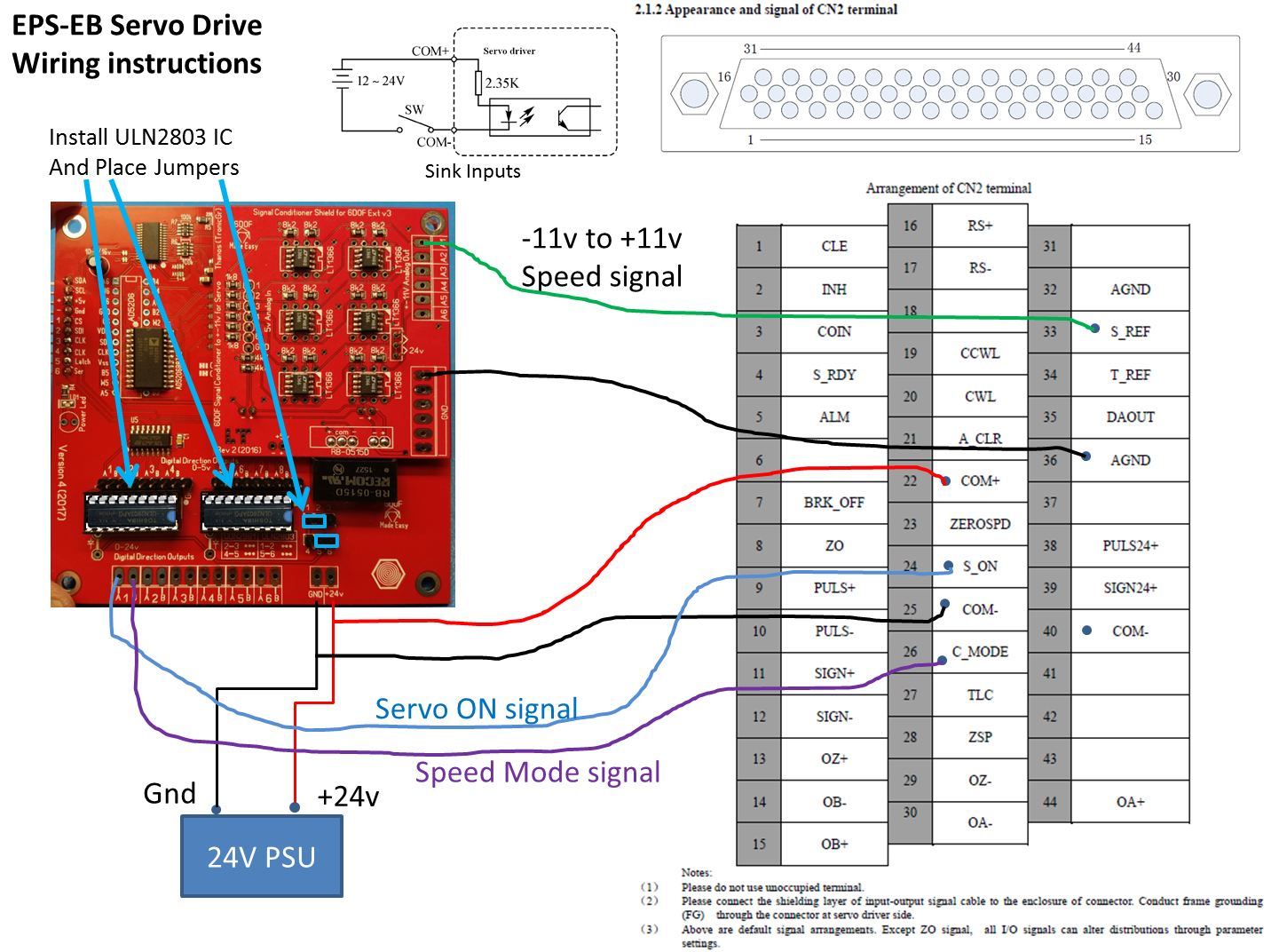
The wiring before the CN2 connector however might look a little intimidating, but its not so bad. The AMC1280USB provides only 3 outputs, Analog speed control (-11v to +11v using the Signal Conditioner), Sink output Servo Enable signal and Zero Speed signal to completely stop the motors when the "Kill motors" emergency switch is pressed.


This is a different servo example that uses C-mode to select analog input


Generic schematic of connections between servomotor and the AMC1280USB controller


The Encoder2Position module however has lots of connection to the CN2 connector like the four connections to the Differential Encoder Outputs and two more Sink outputs that connect to the CWL and CCWL (Forward or Backward rotation prohibited inputs of the CN2). Also the Encoder2Position encoder is interfaced to the two magnetic reed limit switches that needed for the automatic calibration of the actuator during power up. The sink inputs are reversed logic that means they need to be HIGH to detect that the limit switch was activated.


Simplified schematic of the Encoder2Position inputs-outputs
The R1 potentiometer checks and sets the calibration speed once on power up.


The Encoder2Position module features a STM32 F1 processor running at 72Mhz, allowing capture of the fast quadrature encoder pulses, and handles automatically the limit switches of the actuator so you don't have to worry for much except just use the 12-bit analog position signal it outputs (0-5v). On the current linear servomotor I have it measures about 30000 positions for the 200mm stroke, and with the actuator having 500mm/s speed, it means it can capture about 60000 pulses in 500ms time with no problem,

The Encoder2Position module will be available soon on Tindie as soon I finalize the firmware on the test unit. Working on getting the 12-bit (or 16bit) SSI output faster without blocking the quadrature encoder counter interrupts.


For often updates you can subscribe to my YouTube channel:
 https://www.youtube.com/user/tronicgr

You could also contact me by email, although you may have to wait sometimes for days for reply (depending on my spare time and the backlog of messages). If you keep it short to one or two questions I might be able to answer right away:


Thanks
Thanos

San Diego, California  2018


Friday, October 27, 2017

New firmware release and kickstarter update

Hi,

New stable firmware v2.4 update is now available:
https://www.dropbox.com/sh/muf1yn18fs2aqpa/AADi0hOnFfZlP2UAQYURqBFKa?dl=0

-Added Max Motor speed control in Unidirectional output modes for 8-bit and 12-bit outputs. This means you can now control the max motor speed on Sabertooth that use 0-5v analog (with 2.5v center), or Servomotors that use -11v to +11v (with 0v center).
-The direction pins now are active when the PID takes control, so you can use them to enable motor drives that support that function (AC servomotor drives).
-Fixed PID issues (wrong assignment of values in calculations).

This firmware is one of the series of updates pending that will add more functions to the AMC1280USB controller. I'll be releasing new firmware updates adding one function at the time so we can verify each added feature does not undermining existing functions.

Update 11/14/2017
New revision: https://www.dropbox.com/s/ukzaj0qdul5epwp/enc_6dof_AMC1280USB_v2.4_rev3.hex?dl=0
-Fixed max motor speed for 12-bit outputs as it was missing


In other news, the kickstarter PCB's were received from manufacturing and currently undergo final assembly (connectors, LCDs, MCU, 3D print cases parts fit). This involves soldering and manual assembly by hand.

Testing of all controllers will be performed before they are shipped to ensure functionality and quality.

I hope the shipping of the kickstarter rewards will start very soon. Again I apologize for any delays but you will have to understand that is huge effort to manage such project involving a complete product (hardware and firmware).

Here is a video I took a few days ago after I verified the shipment of the PCB's for damages during transport:


Subscribe to my youtube channel for faster updates on the project as well for guides I'll be posting regularly. https://www.youtube.com/user/tronicgr

Thanks

Thanos

San Diego, 2017

Monday, September 11, 2017

AMC1280USB Deluxe Enclosure Colors

Hi all,

The following colors will be available, for the 3D printed enclosure for the AMC1280USB Deluxe to select from:

1. Black
2. Silver
3. Gray
4. Blue (Gray Blue)


Enclosure colors *Blue might be a little Gray-ish


The color of the buttons or the knob will be random but chosen to better fit each enclosure color.


Some cosmetic changes might be implemented on the cases on the front like additional outlines etc, but the basic color will be limited to one of the above. See following video:


Front panel outline example


Virtually any color will still look great, even transparent colors!

Transparent color enclosures


If you need different color enclosure contact me for availability.
tronicgr @ gmail .com  (without the spaces)

Thanks
Thanos


Sunday, September 10, 2017

Kickstarter update - PCB boards are in production!

Hi all,

The manufacturing order of the PCB's for the rewards for the Kickstarter was placed and are in production. All parts are shorted out now, and waiting to have all together for final assembly and testing before they are ready for shipping.

https://www.kickstarter.com/projects/1096461972/6dof-electronic-interface-for-motion-simulator-pla/posts/1959819


Said that, you can always contact me for ordering more of the new AMC1280USB controllers  and check for availability prices. I'll be making extra controllers along the kickstarter rewards but will be available for shipping after all kickstarter rewards are shipped first.


Contact email for orders and inquiries: tronicgr @ gmail .com    (without the spaces)

Thanks
Thanos

Saturday, August 5, 2017

Extending Pre-orders for Kickstarter rewards

Hello,

I received numerous emails from people that either kickstarter could not process their credit cards or missed the kickstarter deadline but were still interested in the kickstarter offer.

https://www.kickstarter.com/projects/1096461972/6dof-electronic-interface-for-motion-simulator-pla/


I'll be giving the opportunity to get the almost the same low prices as in kickstarter for a few reward options. The prices will be a few dollars higher to accommodate for the paypal fees.

THIS OFFER is only valid for pre-orders THROUGHOUT AUGUST!!


You have two options to choose from:


Wednesday, July 5, 2017

AMC1280USB motion controller now on Kickstarter

Hello,

After a long consideration, and given the demand for the motion controller I decided to move on to launch a Kickstarter Campaign for the new AMC1280USB motion controller.


The campaign will allow me to focus more in the firmware side of the project while I can outsource the hardware part of the controller. The Kickstarter edition of the AMC1280USB will be better and have easier placement of connectors (slightly redesigned). If there is lots of interest I might add a few more features that will be announced during the course of the campaign.

https://www.kickstarter.com/projects/1096461972/6dof-electronic-interface-for-motion-simulator-pla


Friday, June 23, 2017

6DOF platforms Video Updates

Hi all,

Here is a sum of the videos of most recent 6DOF platform builds using AMC1280USB for the past year. I'll be adding more in future posts.

Enjoy!

Sim Things

Motion Platform initial tuning
https://www.youtube.com/watch?v=4saOF_0B22w


Gago Meisler - Markus
http://6dof.my.primusnetz.de/
http://6dof.my.primusnetz.de/thanos/

DIY 6DOF Motion Platform - DCS Huey - Oculus Rift
https://www.youtube.com/watch?v=LIsUD1ycosc


Trip Rodriguez

Quick and dirty 6DOF VR Motion sim in DCS World P-51D
https://www.youtube.com/watch?v=piiN3cZw5xY


P-51D Fighter ace in 25 minutes! (Against AI)
https://www.youtube.com/watch?v=xxe-K3aTJdo


Motion VR racing demo- Video is Real Time
https://www.youtube.com/watch?v=w-jaJlwtAAo


Trip's 6DOF motion sim nearly complete
https://www.youtube.com/watch?v=JE7dCvlcduI


Really rough demonstration of the travel on my motion sim
https://www.youtube.com/watch?v=jxACgtbO8vg


Mr Simulator
http://motionsim.freeforums.net/thread/15/6dof-platform


6DOF 13 Ply Motion Simulator - Talking about the Simulator - (Project Cars,Walkthrough)
https://www.youtube.com/watch?v=TlT7Fl3Wk4Y


6DOF 13 Ply Motion Platform - GoPro Sonoma Audi R8 V10
https://www.youtube.com/watch?v=ZmUW-FuwutQ


6DOF 13 Ply Motion Simulator (DIRT Rally)
https://www.youtube.com/watch?v=XnzN2GvjyCQ


Cristiano Lini

6DOF Sim Motion Platform IXab
https://www.youtube.com/watch?v=I6jPhxk9B0I


jmsmsagrada
http://motionsim.freeforums.net/thread/53/boeing-6dof-motion-platform-project


6dof Platform Test 3
https://www.youtube.com/watch?v=OMlXqVtXb7g


Craig Pitt - Seatimes

No Limits 2 - Motion Data Roll Pitch Fix
https://www.youtube.com/watch?v=44qY96ha0Nw


No Limits 2 - test of new Plug in for 360 degree roller coasters
https://www.youtube.com/watch?v=kM3k_ZPgR9c


No Limits 2 - 6DOF Motion Sim Real Test
https://www.youtube.com/watch?v=BBG5m72Zmf8


Michael Hensen
http://motionsim.freeforums.net/thread/167/dutch-6-dof


simulator 1
https://www.youtube.com/watch?v=dbdjtZSI7C4


Race sim take 2
https://www.youtube.com/watch?v=WtxHCngw4Xk


Thanks for watching!


Thanos
San Diego, 2017