
The AMC1280USB controller supports all kind of motors and driving protocols (RC servos, DC motors, AC motors, Brushless Servomotors etc), each type needs its driver, like DC motor needs h-bridge, AC motors need VFD inverter drive, for RC miniservos you can use the Pololu miniservo driver that attaches right on the AMC1280USB controller. One AMC1280USB controller is able to control up to 6 motors, thus possible to be used for a variety of DOF simulators not only 6DOF. Best feedback sensors are the ones for 180 degrees rotation with analog output for 6DOF.
The Atmega1280 microcontroller that accompanies the AMC1280USB (black board sandwiched under it) is not an arduino compatible one. It has custom secure bootloader that allow me to distribute free firmware updates to existing AMC1280USB owners over the internet.
The motion controller is designed to work with both racing and flight simulation software (Ian's 6DOF BFF, X-sim-3 , Simtools). The best motion software to use at the moment is Ian's 6DOF BFF motion software that supports both worlds, as well now real world interfacing (via 9DOF sensor array, see update Jan 2015). See a short test video of the wireless sensors here: https://www.youtube.com/watch?v=idTS2qIN75Q
And the latest
achivement here: https://www.youtube.com/watch?v=2yCRIW763x8
Also have a look at
Fabian's new site that covers many existing technologies that can be used
together for interesting uses of 6DOF motion simulator: http://vrmotion.rocks/wordpress/
And some informative
videos and blog writeup about Fabian's innovations:
The xsim 6DOF Thanos plugin works only on AMC1280USB as it has autodetection function to find it connected on the system. Ignacy has an updated version of it available here: http://motionsim.freeforums.net/thread/198/6dof-control-plugin-development
For x-sim3 there is a new 6DOF plugin under development by Ignacy that will be available here: http://hexpod.xyz/ (you can try his free beta version from there as well)
The best way to
proceed at this time is to make a platform like Fabian here:
Read his blog, he
posted details about the materials he used, motor size as well what VFD
inverters. Check out his free AMC1280USB Configurator software as
well.
Apart from that, you
may see more examples with link to their project threads here:
Best example is Steven's
platform: http://motionsim.freeforums.net/post/557/thread
DoctorD platform example: http://x-sim.de/forum/viewtopic.php?t=1599
DoctorD platform example: http://x-sim.de/forum/viewtopic.php?t=1599
And Mike's Flight
Simulator 6DOF platform: http://motionsim.freeforums.net/thread/53/boeing-6dof-motion-platform-project
Generally the cost for parts for a 6DOF platform capable of 250-300kg dynamic loads using AC motors, is about $4500 or less if you can get good deals from suppliers for the needed industrial equipment. Other solutions based on DC motors are less expensive but can handle less load.
Example with AC
motors for 300kg to 400Kg load:
1.5HP AC motors:
MTR-1P5-3BD18
1HP 100:1 worm gearboxes:
WGA-75M-100-H1
2HP VFD
inverter: WJ200-015SF
And Braking resistors
To calculate the load capacity of the platform for different motors / gearboxes you may use the excel template that can be found here: http://motionsim.freeforums.net/post/3945/thread
To calculate the load capacity of the platform for different motors / gearboxes you may use the excel template that can be found here: http://motionsim.freeforums.net/post/3945/thread
All worm gearboxes have some backlash, that might vibrate the platform while moving down, The best way to deal with this is to add springs to each arm to keep the gears in contact and avoid the freefall acceleration during gravity: http://motionsim.freeforums.net/post/3781/thread
Another solution,
though more expensive would be to use linear servomotor actuators for 2000Kg
dynamic load like here:
See his Youtube
channel for more videos of his professional builds: https://www.youtube.com/user/leandroter7
The clearpath motors solution is good but more technical that others to achieve. The hexapod design is compact, but it might cost a bit to find the proper gearboxes that can survive the almost 90% duty cycle of the motion and the fast reversing of the motor for the positioning, See the latest video of this platform while testing on the motion software:
Integral hp models (100-240 VAC input)
https://www.teknic.com/products/clearpath-brushless-dc-servo-motors/clearpath-mc/mcvc-models
The great improvement is that they provide 2-3 times more torque and you don't need the power supply anymore, they get power from 110v or 220v and the larger models have 56C face that can be mounted to normal 56C size industrial worm gearboxes for the 6DOF platform
If you don't have access
to high voltage power (220v) or you consider it unsafe, you can always check
out this DC motor solution with linear actuators here:
For connections examples of AMC1280USB with AC motors see the support files library (almost complete) here
Or more specifically
here: https://www.dropbox.com/sh/06y2wmizl998l6g/AAB6EnvyW28odJNxC5NwAqjea?dl=0
The usual RPM after
reduction of the gearbox for 6DOF platforms is 10-15RPM.
The AMC1280USB output
signals can be Analog 0-5v or 0-10v or -11v-+11v or PWM
0-5v logic (all cases can be bi-directional or Unidirectional). The
position feedback is analog 0-5v, any type of sensor within these limits can be
used.
For servo motors, you will need analog signal -11v to +11v that the new 6DOF extension board v4 can output using a signal conditioner shield for 6 signals.
The signal conditioner shield uses expensive but accurate rail to rail amplifiers on it. You can use this analog out signal for either bi-directional mode (analog signal for both speed and direction with sensor feedback) or Absolute position mode (-11v to +11v represents 4096 positions of the actuator)
See more info on using Servomotors (and linear actuators with the new Encoder2Position module) here:
http://motionsim.blogspot.com/2018/02/using-linear-ac-servomotor-actuators.html
Sensor Options and addons:
a. 6x Analog 10-bit Magnetic contactless position sensor 180 degrees: http://www.digikey.com/product-detail/en/6127V1A180L.5FS/987-1392-ND/2620661 (Preferred with AC motors or DC motors with crank arm gearbox like this). You can see these next to the AMC1280USB controller on the photo here.
There is a better quality version of this sensor with ball bearings that costs more but its durable to axial loads:
b. 6x Analog 10-bit magnetic contactless 10-turn position sensors for linear actuators:
https://www.digikey.com/product-detail/en/bourns-inc/AMM20B5 A1CLASL380/AMM20B5A1CLASL380-ND/3868206
Or
3D printed String Potentiometer housing
c. 6x ENCODER ABS MAGNETIC 12-BIT 6MM - AEAT-6012-A06
3D printed Mounting: http://www.thingiverse.com/thing:1926094
And 3D printed mount on the gearbox: http://www.thingiverse.com/thing:2068945
As described here: http://motionsim.freeforums.net/post/4071/thread
More info about them: http://motionsim.freeforums.net/thread/234/firmware-2-beta
These sensors are five wire digital, and have a Miniature picoblade connector. Here are the additional links to the wires for the connector needed:
https://www.digikey.com/products/en?keywords=WM1723-ND
12" PRE-CRIMP 1852 GREEN (10 pieces)
https://www.digikey.com/products/en?keywords=0500798000-12-G8-ND
12" PRE-CRIMP 1852 WHITE (10 pieces)
https://www.digikey.com/products/en?keywords=0500798000-12-W8-ND
12" PRE-CRIMP 1852 RED (10 pieces)
https://www.digikey.com/products/en?keywords=0500798000-12-R8-ND
12" PRE-CRIMP 1852 BLACK (10 pieces)
https://www.digikey.com/products/en?keywords=0500798000-12-B8-ND
d. Another solution if you are using AC servomotor would be reading their internal quadrature encoders. See how is can be done in the following blog post: http://motionsim.blogspot.com/2018/02/using-linear-ac-servomotor-actuators.html
e. 1x Pololu Micro Serial Servo Controller (for creating miniservo 6DOF platform model for testing) http://www.pololu.com/product/207
As this is now obsolete new alternative:
https://www.pololu.com/product/1350You can download here the preliminary version of the manual of AMC1280USB I did so far (I'll do more when I get some spare time these days as I keep adding features and functions still):
Following the release of AMC128USB v2.0 (2017) I'll be making new manual that will cover all new functions and operating modes.
----------------------------------------------------------------------------
Here are some FAQ:
Q. Does the arduino come included with the board and extension board and if it does will it be programmed also ?
A. The Atmega1280 boards that look like Arduino boards are included. I only use that for easier manufacturing of the controller, essentially using the FT232RL and Atmega1280 chips on them that are hard to include on a single board. Also its easier to separate and send replacements boards to customers if something goes bad. That board comes programmed and ready to be used:
-----------------------------------------------------------------------------
Q. I did not understand well ( The AMC1280USB uses a custom firmware that is not compatible with arduino, that allows me to share free updates to all existing owners of the controller, with improvements or additional features.)
A. The custom Bootloader I use, can be updated with a program that I provide. See this video: New guide: Updating the firmware on AMC1280USB v2
If you see the LCD display empty squares on the first line of the LCD, the AMC controller it probably in Bootloader mode and you will have to load the latest firmware again.

To recover it, download the latest firmware from here:
And the UDB tool from here:
https://www.dropbox.com/sh/n2owe6yo5jon440/AAC5GsAmzcYsnWpdb2j73P23a?dl=0
And follow the instructions on the video:
https://www.youtube.com/watch?v=AvzM-5D5PxM
-----------------------------------------------------------------------------
Q. What is the games that compatible with the board for 6DOF ?
A. That depends on the motion software used. The controller just receives motion data from the motion software. You can see the supported motion software for details on the supported games:
a. Ians BFF 6DOF motion software: http://
c. Simtools: https://www.
-----------------------------------------------------------------------------
Q. I am going to use an AC motors, Is the type of the inverter makes any difference ?
A. I recommend using the Hitachi WJ200, These are the most common used from many customers that use 220v AC motors: http://motionsim.
But you can use any other VFD inverter as long it can accept Positive SOURCE signals for direction. I recommend using the Hitachi ones as the settings are well explored and known whether with other VFD inverters you will have to experiment with a little bit to get it right.
-----------------------------------------------------------------------------
Q. Am I going to need any further programming after connecting the 6 motors and inverters with the board ?
A. Answered that already above. No Programming, just set a few parameters on the AMC1280USB and the VFD inverters. You can consult the support forum for that or look examples available there.
-----------------------------------------------------------------------------
Q. It's linear actuators I am building. I don't have much equipment. My aim was to get the motor, driver and controller working before I spend any more money.
A. In that case you will need to use some string linear potentiometer for position feedback that can be placed externally along the actuator. I have a solution for that using 3D printed case: http://www.thingiverse.com/ thing:1926226
There are links to the potentiometers you can use with it that can be attached to the AMC1280USB.
I can print the 3D parts for them and include them to the package along the retractable spring mechanisms. Its easy to put them together yourself, I have some photos of the assembly procedure.
-----------------------------------------------------------------------------
Q. Also you stated:
"AMC1280USB can only control the Servo drives with Analog -11v to +11v signal which does both direction and speed in a single signal." I am counting on my analog input D+ D- , -10V - +10V in speed control to be able to do that. So the -10V will turn it anti clockwise" and that "The AMC1280USB will keep track of the servomotor position using external position sensors."
A. That is correct, you don't need the DIR signals. The Analog in signal will automatically handle the change of speed and direction as well.
-----------------------------------------------------------------------------
Q. Also nearly all servo drivers I see is 10v. Will 11Volts burn the driver out?
A. The Servo Signal conditioner actually outputs max 10.5v which can be limited to less that than by setting the MAX Motor Speed setting on the AMC1280USB LCD menu. https://www.youtube.com/ watch?v=NeToy2GsP18
-----------------------------------------------------------------------------
Q. CW, CCW pins is rotation of the motor. Am I right in thinking I do not need to use this as I will be relying on the analog input -10c - +10v?
A. Already answered that, no need to use the direction inputs if using analog signal.
-----------------------------------------------------------------------------
Q. p.s My servo motor has a spring loaded brake to hold a load when power is stopped. It is DC24V brake. Pin 30 and 31.
A. I'll show you how to hook up some simple relays to the Digital outputs of the AMC1280USB to release the brake for each motor when there is motion command. You can use a cheap Relay board like this one: http://www.ebay.com/itm/ 5v-Eight-8-Channel-DC-5V- Relay-Switch-Module-for- Arduino-Raspberry-Pi-ARM-AVR-/ 231682185473?hash= item35f1559901:g: uWQAAOSwFnFV9O0w
Actually you will need two of those relay boards for 6 servomotors to hook up also the "Enable Motor" of each servomotor during power up of the system.
-----------------------------------------------------------------------------
Q. How quick can you send this stuff. I know you said you was busy so excuse me asking you that and all these other questions because my understanding needs to be clear.
A. The lead time to have the AMC1280USB v2.1 controller and the Servo Signal conditioner ready is 30-40 days. There is still lots of manual labor involved to complete the controllers and test them before they are ready for shipping.
-----------------------------------------------------------------------------
Q. We are able to control the positions of the motors, but we have one more issue that we have not been able to solve. The motors always rotate in the opposite direction than we expect them to. For example, when using the x-sim plugin, a positive heave motion causes the platform to move down. Changing either the polarity of the feedback pots or the sensor direction setting on your board causes the system to become unstable. This makes sense to me since the motor will rotate in the same direction as the error, causing the error to increase rather than rotating in the opposite direction and approaching the desired position. However, if I change both the polarity and the sensor direction setting, it seems to me that the system should remain stable, but rotate in the opposite direction. When we tried this though, we found that it is stable, but that the rotation direction was unaffected. I am not sure how we can change the rotation direction so that an upward movement in the software results in an upward movement of the platform. What can we do to achieve this?
A. The correct change would be:
1. Connect all potentiometers with same orientation ( all bars move to the same direction for CW or CCW rotation of the potentiometers).
2. Make sure the motors follow the potentiometers direction. If not, swap the A - B connections on the 6DOF ext board for that motor until the motor is stable.
3. You can choose the direction of the motors using the "Sensor Direction" option in the LCD menu. It will change the direction of the motors in pairs. If after change some motors run away from the potentiometers positioning, Swap the A - B direction connection for those motors.
-----------------------------------------------------------------------------
Q. We were able to make some progress on our own. It turns out that the vfd is a sink input. I meant to buy one that was a source input. I saw in the manual that the board can be set up to handle sink inputs by switching the two chips on the 6DOF extension board and moving a few jumpers. I have a couple questions about how to implement this though. We have the ULN2803 darlington arrays and a 15 V source, but I am not sure where the 15 V source connects to the board. Also, I was able to determine that VI should be referenced to the ACM terminal, but that 'for' and 'rev' should sink to the DCM terminal. It seems to me that the board needs references to both ACM and DCM, but I'm not sure how to properly wire these connections to the board.
A. It seems you will have to join the two grounds (ACM and DCM) in order to make it work. See here for details: http://motionsim.freeforums.net/thread/147/help-sink-mode
Also you can connect the 15v positive to the middle pin of the connector like on the photo (after you remove the jumper that exists there:
-----------------------------------------------------------------------------
Q. The 6DOF ext board has a 24v input terminal. What power supply I should connect to it?
A. You can use any 24v PSU, that is rated at least for 1A. Something like this would work great:
"110V/220V AC to DC 24V 1A 24W Switch Power Supply Driver,Power Transformer"
-----------------------------------------------------------------------------
Q. All is connected as instructed in the connection diagram but I get no motion from the motor:

A. I think you should try to activate manually the inputs of the VFD inverter without the AMC1280USB connected, just to make sure you have set the terminal correctly.
You will need one simple 10k potentiometer (NOT the Magnetic position sensor!!! its only rated 5v!!!) wired as in the schematic (with the middle leg of the potentiometer that called wiper connected to the AI1). Also you will need two simple switches (or buttons) to wire between the 24v PSU and the S1 and S2 terminal inputs. Use the same 24v PSU from you have been using for the AMC1280USB.

-----------------------------------------------------------------------------
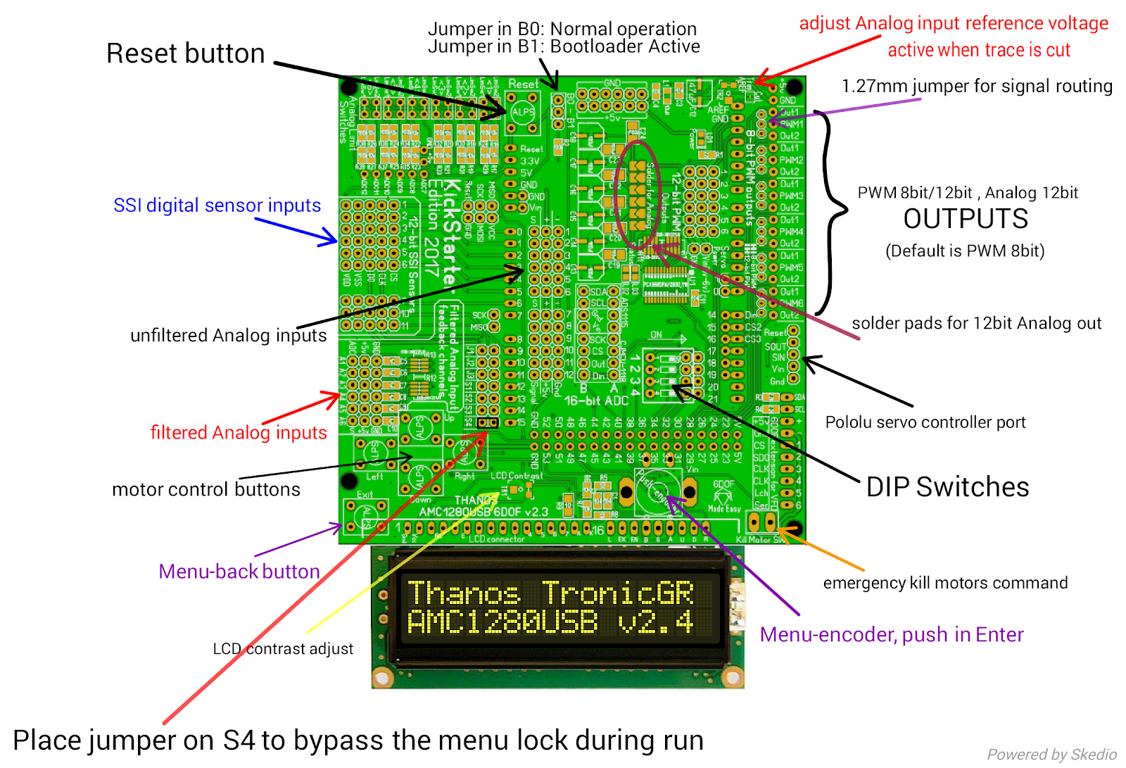
Q. What is the function of the five buttons on the front panel of the AMC1280USB?
A. The four buttons on the front manually position the motors to 80% position and 20% position for testing (UP, DOWN,LEFT,RIGHT). The UP/DOWN commands all motors the same, the LEFT/RIGHT commands half motors to 20% and other half to 80%.
The fifth button on bottom is a "Back" button for the LCD menu, if you want to escape from a setting without saving.
-----------------------------------------------------------------------------
Q. I cannot setup the Sabertooth drives, they are not stable and have very little motion range or run-away.
A. The Sabertooth drives have unidirectional driving mode that means if they receive 2.5v signal they will be stop, if voltage 0v-2.49v the motor moves clockwise with variable speed and 2.51v-5v the motor moves counter-clockwise with variable speed.
So the AMC1280USB has to have these settings:6DOF start Pos --> 50 (this indicates the 2.5v stop position of the sabertooth drives)
Step -->99 ( this should be left high as required for the sabertooth drives)
Timeout -->10 ( This is the timeout to return the actuators to 50% position as soon there is no motion data from the PC )
The output parameter should be set to 8-BIT / Unidirectional mode (0-5v output on the 6DOF ext board).
The Motor max speed (offline and online) should be set to 100, to be able to drive the output signal entirely in the 0v to 5v region, because of the nature of the Unidirectional control method.
Also change the feedback limit parameter to 1% to be able to reach the whole range of the actuator.
Now the analog feedback potentiometers are needed for the PID to calculate the position of the motors and how much the controller needs to deviate the 0-5v analog output from 2.5v to drive the speed of the sabertooth drives to each direction. If you move the the potentiometers manually and measure the output you will see less voltage swing of the max motor speed and feedback limit values are not as mentioned above.
To avoid run-away issues, make sure you power on the AMC1280USB first and then power the Sabertooth drive. Similar, turn off the sabertooth drives first and then disconnect power to the AMC1280USB controller.
-----------------------------------------------------------------------------
AMC1280USB with 6DOF: support files library DropBox (almost complete) here
-----------------------------------------------------------------------------
Some diagrams and media related to the AMC1280USB controller:
AMC1280USB with 6DOF: support files library DropBox (almost complete) here
-----------------------------------------------------------------------------
Some diagrams and media related to the AMC1280USB controller:

Some helpful connection diagrams for the kickstarter version AMC1280USB can be seen here:


You can contact me at: Tronicgr @ Gmail .com (minus the spaces, which are used to defer bots)

Simple conversion of 8-bit PWM to Analog voltage

Sabertooth DC motor drives

GS1 VFD inverters

TECO VFD inverters

Connecting Linear potentiometers with 4 pin connectors
You can contact me at: Tronicgr @ Gmail .com (minus the spaces, which are used to defer bots)
Thanos,

No comments:
Post a Comment